Three-Phase Isolation Transformer
 Control Transformer
 Medical IT Isolated Power System
 Marine Transformer
 Tunnel Transformer
 High Current Transformer
 Automatic Voltage Regulator
 Oil Immersed Voltage Regulator
Leave Your Message
Choosing the best High Current Transformer in 2026 requires more than comparing catalog prices. Global buyers must examine current ratings, insulation levels, accuracy classes, thermal performance, and installation conditions. A transformer serving a steel mill may face severe heat, vibration, and frequent overloads. A unit installed in a renewable energy substation may prioritize compact design, low losses, and reliable outdoor protection.
Common options include oil-immersed, cast-resin, air-core, and specially engineered bar-type transformers. Each type suits different operating environments. Cast-resin models offer strong fire resistance for indoor facilities. Oil-immersed designs often support high-capacity systems and demanding cooling requirements. Air-core solutions can reduce saturation risks in selected protection applications. However, no type is universally superior. The correct decision depends on fault levels, space, maintenance skills, ambient temperature, and required measurement accuracy.
Professional buyers should request verified test reports, factory quality records, and clear compliance details. IEC and IEEE references can guide evaluation, but local grid requirements still matter. Supplier experience also deserves close attention. A manufacturer that explains burden calculations and short-circuit withstand limits is usually more dependable than one offering only a low quotation. Still, technical documents can contain gaps. I have seen projects overlook cable length, terminal temperature, or secondary grounding. Small omissions can create expensive delays. Careful review remains essential.
This guide compares leading High Current Transformer types for global purchasing decisions. It focuses on practical performance, lifecycle value, safety, and supply reliability. The recommendations are useful, but site verification should never be skipped. Real conditions decide.
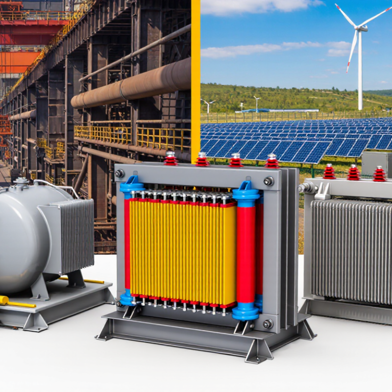
High-current transformers convert and control substantial AC loads at 50/60 Hz. Global buyers commonly compare dry-type, cast-resin, oil-immersed, and current-transformer designs. Ratings from 1 A to 10,000 A require careful interpretation. A 1,000 A primary rating does not describe thermal capacity alone. Engineers must also check voltage, insulation level, duty cycle, frequency, impedance, and short-circuit withstand.
The IEC 61869-2 standard defines key performance requirements for instrument current transformers, including accuracy and protection behavior. For power distribution units, IEC 60076 remains a central reference. The U.S. Department of Energy’s 2024 distribution-transformer analysis separates no-load losses from load losses, showing why efficiency cannot be judged from one number. Small mistakes matter. A poorly matched CT can saturate during faults and distort relay signals. That risk deserves more attention.
The IEA Electricity 2024 report projects global electricity demand growth through 2026, increasing pressure on substations and industrial networks. Buyers handling 50/60 Hz systems should request certified test data, temperature-rise results, partial-discharge levels, and routine-test records. Dry-type units suit indoor sites where fire risk and maintenance access matter. Oil-immersed units often support higher power density, but installation conditions become more demanding. For 1–10,000 A applications, compare continuous current with peak current, not only the nameplate rating. A neat specification sheet can still hide a weak assumption. Verify the real load profile before selecting the “best” transformer type.
| Transformer Type | Typical Primary Current Rating | Typical Secondary Output | Common Accuracy Classes | Typical Burden Range | Typical System Voltage | Recommended Applications | Key Selection Considerations |
|---|---|---|---|---|---|---|---|
| Metering Current Transformer | 1 A or 5 A | 0.10.20.5 | 2.5–15 VA | Up to 36 kV, depending on insulation design | Revenue metering, panel meters, energy monitoring and power-quality measurement. | Specify accuracy at the actual operating current, rated burden, frequency and required insulation level. | |
| Protection Current Transformer | 1 A or 5 A | 5P105P2010P20PX | 5–30 VA | Up to 36 kV, with higher-voltage designs available | Overcurrent, differential, earth-fault and distance-protection systems. | Check the accuracy-limit factor, knee-point voltage, winding resistance and relay burden to avoid saturation during faults. | |
| Bar-Type Current Transformer | 1 A or 5 A | 0.55P1010P20 | 5–30 VA | Usually low-voltage switchboards; medium-voltage versions are also available | High-current busbars, switchgear, motor control centers and generator terminals. | Confirm busbar dimensions, phase spacing, thermal short-time current and continuous-current rise. | |
| Window-Type Current Transformer | 1 A or 5 A | 0.51.05P10 | 2.5–30 VA | Commonly up to 1.2 kV for low-voltage systems | Installation around insulated conductors, busbars and existing power-circuit conductors. | Measure the conductor or busbar cross-section and maintain the required clearance around the magnetic core. | |
| Split-Core Current Transformer | 1 A, 5 A or low-voltage electronic output | 0.51.03.0 | 1–15 VA for conventional outputs | Typically up to 600 V or 1.2 kV, depending on construction | Retrofit metering, energy-management systems and installations where conductor disconnection is impractical. | Core-joint alignment affects accuracy; the clamp must close completely and be installed in the correct direction. | |
| Solid-Core Toroidal Current Transformer | 1 A or 5 A | 0.20.55P10 | 2.5–20 VA | Low-voltage and medium-voltage designs are available | Compact switchboards, precision metering, protection panels and residual-current measurement. | Use a centered conductor where possible; verify aperture size, insulation clearance and the effect of nearby magnetic fields. | |
| Bushing Current Transformer | 1 A or 5 A | 0.20.55P20PX | 5–30 VA | Common in medium- and high-voltage equipment | Power transformers, generator transformers, dead-tank circuit breakers and high-voltage bushings. | Confirm bushing dimensions, insulation coordination, polarity, core allocation and the number of available cores. | |
| Residual-Current / Zero-Sequence CT | 1 A, 5 A or electronic residual-current output | Class 1.0Class 3.0Protection class | 1–15 VA | Usually low-voltage; medium-voltage versions are available | Ground-fault detection, earth-leakage protection and residual-current relays. | All phase conductors and the neutral, if applicable, must pass through the core together; the protective-earth conductor normally does not. | |
| Multi-Ratio Current Transformer | 1 A or 5 A with selectable taps | 0.55P105P20 | 5–30 VA, depending on selected ratio | Low-voltage through medium-voltage applications | Projects where future load growth, multiple protection settings or several ratios are required. | Specify the usable ratios, tap arrangement, accuracy and burden for every tap—not only the highest ratio. | |
| High-Temperature / Cast-Resin CT | 1 A or 5 A | 0.55P1010P20 | 5–30 VA | Low-voltage and medium-voltage switchgear | Industrial plants, renewable-energy systems, humid environments and indoor or outdoor switchgear. | Review ambient temperature, thermal class, resin insulation, altitude correction, creepage distance and enclosure rating. |