Modern facilities are carrying more sensitive electrical loads than ever. The IEA’s Electricity 2024 report projects global electricity demand to grow by an average of 3.4% annually through 2026. That growth increases pressure on factories, data centers, hospitals, and commercial buildings to control electrical noise, grounding problems, and equipment damage.
A Three Phase Isolation Transformer separates the primary and secondary circuits through magnetic coupling. It transfers three-phase power while reducing direct conductive paths between source equipment and connected loads. This arrangement can limit common-mode disturbances, support grounding strategies, and protect critical systems from some upstream faults. It is not a cure-all. Incorrect sizing can still create voltage drop, excessive inrush current, overheating, or poor motor starting performance.
In practical commissioning work, engineers examine more than the nameplate voltage. They check kVA capacity, impedance, frequency, insulation class, temperature rise, shielding, and neutral-ground bonding. IEC 60076 provides the main international framework for power-transformer design and testing, while IEEE C57.12.00 defines general requirements for liquid-immersed and dry-type transformers. These standards improve consistency, but site conditions still matter. A clean laboratory result may not predict behavior beside variable-speed drives or welding equipment.
This guide explains how a Three Phase Isolation Transformer works, where it adds measurable value, and where its limitations become important. Readers will also see how harmonics, fault protection, maintenance access, and lifecycle efficiency influence selection. The details may appear technical. They are practical. A well-chosen transformer should make the electrical system quieter, safer, and more predictable—not merely larger.
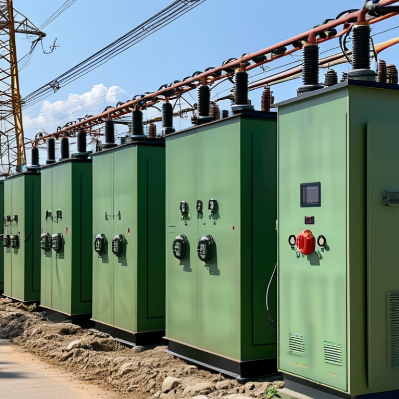
A three-phase isolation transformer transfers electrical energy between separate primary and secondary windings. The windings share magnetic flux, but they do not connect electrically. This separation can reduce unwanted ground-loop currents, limit electrical noise, and protect sensitive equipment from disturbances on the supply side. Three-phase units serve motors, data equipment, medical systems, and industrial control panels. They usually contain three transformer cores or a carefully designed common core. The enclosure may be dry-type and air-cooled, or another design may suit demanding installations.
The input and output can use different voltage levels, phase arrangements, or winding connections. Common configurations include delta and wye connections. A wye secondary may provide a neutral point, but that neutral still requires correct bonding and grounding. Isolation does not automatically make a system safe. It does not remove overloads, poor wiring, or short-circuit risks. That assumption is wrong.
Sizing requires more than matching the voltage. Engineers check the connected load, starting current, duty cycle, ambient temperature, harmonic content, and available fault current. A motor can draw several times its running current during startup. The transformer must tolerate that event without excessive voltage drop. During commissioning, technicians verify phase sequence, insulation resistance, winding temperature, grounding continuity, and output voltage under load. Small details matter. Incorrect phase rotation can reverse a motor. Undersized conductors can overheat. Even experienced designers should review the installation conditions, because a theoretically correct transformer may perform poorly in a real, crowded electrical room.

What Is a Three Phase Isolation Transformer?
A three-phase isolation transformer transfers electrical power through magnetic fields, not direct conductor contact. Its primary winding receives three-phase alternating current. The changing magnetic flux then induces voltage in the secondary winding. This process preserves the supply frequency while electrically separating both circuits.
That separation helps limit shock paths, reduce some common-mode noise, and protect sensitive equipment from upstream disturbances. Engineers may choose delta-delta or delta-wye windings. A delta-wye design can provide a new neutral point and create a 30-degree phase shift. The result depends on the winding ratio, grounding method, load balance, and transformer impedance. Real installations are less tidy.
The U.S. Department of Energy’s 2024 distribution-transformer rule estimates about 3.6 quadrillion British thermal units in energy savings over 30 years. That figure covers regulated distribution transformers broadly, not every isolation transformer. It still shows why core loss, copper loss, and loading deserve attention. IEC 60076-1 and IEEE C57.12.01 provide useful technical frameworks for transformer design and testing.
Tips: Check the inrush current before selecting protection. Measure all three phase currents during commissioning. An isolated secondary is not automatically safe; it still needs correct bonding, grounding, shielding, and overcurrent protection. A transformer can be correctly sized and still disappoint when harmonics, heat, or poor ventilation were ignored. The explanation has limits: isolation reduces certain risks, but it cannot correct every power-quality problem.
A three-phase isolation transformer transfers electrical energy between separate windings. It reduces direct electrical connection between the source and the load. This separation can limit fault-current paths, reduce common-mode noise, and support safer maintenance practices.
The core and windings form its main magnetic assembly. The laminated steel core guides flux and helps control energy loss. Three primary windings connect to the incoming phases. Three secondary windings supply the isolated output. Insulation, cooling channels, terminals, and a protective enclosure also matter.
The core matters.
Electrical configuration determines how the transformer behaves. Common connections include delta-delta, wye-wye, and delta-wye. A wye secondary can provide a neutral point for line-to-neutral loads. A delta connection may handle certain unbalanced loads more effectively, but it does not naturally provide a neutral. Delta-wye designs also create a phase shift, which engineers must include in system studies. Incorrect phase identification can cause serious equipment problems.
During field inspections, technicians should verify winding ratios, terminal markings, grounding, insulation resistance, and phase sequence. Protective devices must match the transformer’s inrush current and rated capacity. Ventilation should remain clear, especially in warm electrical rooms.
Small errors matter.
I would not treat the nameplate as the entire design; actual load diversity, harmonics, ambient temperature, and future expansion can change performance. A qualified professional should confirm the configuration against applicable electrical requirements before energization.
A three-phase isolation transformer transfers electrical power between windings without a direct conductive connection. It separates the source from the load while maintaining three-phase supply. This design can reduce common-mode noise, limit fault propagation, and improve voltage stability in demanding facilities.
The main benefit is cleaner, safer power for sensitive equipment. Hospitals use isolation transformers around imaging and operating-room systems. Factories apply them to variable-speed drives, robotics, CNC machines, and control panels. Data centers also use them where harmonics and switching noise can disturb servers. The need is growing. The International Energy Agency’s Electricity 2024 report estimates that data centers used about 460 TWh globally in 2022. Their consumption could exceed 1,000 TWh by 2026. Stable power quality is becoming harder to ignore.
Efficiency still matters. A transformer consumes energy through winding resistance and core losses, even when the load is light. The U.S. Department of Energy estimated that updated distribution-transformer standards could save 3.6 quadrillion Btu over 30 years and avoid about 340 million metric tons of carbon dioxide. Those figures cover distribution transformers broadly, not every isolation model. That distinction matters. Engineers should compare no-load losses, impedance, temperature rise, short-circuit strength, and harmonics before selecting a unit. Oversizing may improve future capacity, but it can increase standby losses and purchase costs. Isolation is useful, not magical. Poor grounding or incorrect protection can still create dangerous conditions.
A three-phase isolation transformer transfers power between separate three-phase circuits while maintaining electrical isolation. Its three sinusoidal phase voltages are separated by 120°, which helps provide smooth power delivery to industrial equipment, motor drives, control systems, medical equipment, and sensitive electronics.
Main benefits: galvanic isolation, reduced electrical noise and common-mode disturbances, improved safety, and compatibility between different voltage systems. The chart shows normalized ideal phase voltages over one complete 360° cycle; actual voltage magnitude depends on the transformer rating and system configuration.
What Is a Three Phase Isolation Transformer?
A three-phase isolation transformer transfers power through magnetic coupling. Its primary and secondary windings remain electrically separate. This arrangement can reduce conducted noise and limit fault energy between circuits. It does not guarantee shock protection. Secondary grounding, overcurrent protection, and enclosure design still require careful engineering. NFPA 70E emphasizes documented risk assessment, de-energization, and verification before electrical work begins.
Selection starts with load behavior, not only rated capacity. Confirm input and output voltage, frequency, kVA, phase sequence, impedance, inrush current, and harmonic content. Motors may demand several times their running current during startup. Nonlinear loads can also increase winding temperature. Allow practical headroom, but excessive oversizing may increase losses and cost. The U.S. Department of Energy’s 2016 distribution-transformer rule projected 3.63 quadrillion Btu in energy savings over thirty years. Efficiency matters continuously.
Maintenance should include visual inspection, terminal torque checks, temperature trending, and cleaning around ventilation paths. Look for hot spots, cracked insulation, unusual humming, moisture, or a burnt smell. Infrared scans work best under meaningful load. Insulation-resistance testing requires proper isolation and qualified personnel. IEEE guidance supports condition-based evaluation, yet schedules alone can become mechanical. A perfect checklist can still miss a loose connection. Reconsider the design after major load changes, repeated trips, or unexplained temperature rise.
| Data Dimension | Typical or Recommended Information | Safety, Selection, or Maintenance Relevance |
|---|---|---|
| Primary function | Provides galvanic isolation between a three-phase source and load through separate primary and secondary windings. | Helps reduce the transfer of common-mode electrical noise and limits a direct conductive path between the source and load. It does not replace grounding, overcurrent protection, or lockout procedures. |
| Number of phases | Three phases, normally identified as L1, L2, and L3 on the input and corresponding phase terminals on the output. | The transformer must match the supply system and the load phase arrangement to prevent voltage imbalance and incorrect connections. |
| Common voltage arrangement | A 1:1 ratio is common for isolation, while step-up or step-down ratios are selected when voltage conversion is also required. | Confirm primary voltage, secondary voltage, frequency, tap settings, and allowable voltage tolerance before purchase or installation. |
| Frequency | The transformer frequency rating must match the system frequency, commonly 50 Hz or 60 Hz. | Operating at an unsuitable frequency can increase magnetizing current, heating, noise, or core losses. |
| Connection options | Common arrangements include delta-delta, wye-wye, delta-wye, and wye-delta, depending on system requirements. | Connection type affects neutral availability, phase displacement, grounding method, harmonics, and compatibility with the downstream distribution system. |
| Neutral conductor | A neutral is available only when the selected winding configuration provides a neutral point, such as a grounded wye secondary. | Do not assume that an isolation transformer automatically provides a neutral. Verify the wiring diagram and grounding arrangement. |
| Power rating | Specified in VA or kVA. Select a rating at least equal to the calculated continuous load, with additional capacity for starting and inrush current. | Undersizing can cause excessive temperature rise, nuisance tripping, voltage drop, shortened insulation life, and premature failure. |
| Load calculation | For a balanced three-phase load, apparent power can be estimated as: S = √3 × VLL × IL. | Use the line-to-line voltage and line current consistently. Include motor starting, rectifier, capacitor, and other nonlinear-load characteristics. |
| Impedance | Transformer impedance is commonly expressed as a percentage on the nameplate; the correct value depends on voltage regulation and fault-current requirements. | Higher impedance generally limits fault current but can increase voltage drop. Coordinate the value with protective-device operation and system studies. |
| Insulation and dielectric strength | Verify insulation class, temperature class, dielectric withstand rating, and insulation resistance requirements in the technical documentation. | These ratings indicate the transformer's ability to withstand operating temperature and electrical stress between windings and to ground. |
| Cooling method | Dry-type units commonly use natural air cooling; larger units may use forced-air cooling or liquid insulation systems. | Maintain the required ventilation clearance and never block air passages. Cooling conditions directly affect permissible loading and service life. |
| Enclosure and environment | Select an enclosure suitable for indoor or outdoor installation, with an ingress-protection or enclosure rating appropriate to dust, moisture, and chemicals. | Environmental conditions can accelerate corrosion, contamination, tracking, and insulation deterioration. |
| Grounding and bonding | Bond the metallic enclosure to the protective earth. Ground the secondary neutral or other designated point only as required by the system design and applicable electrical rules. | Incorrect bonding can create shock hazards, unwanted circulating currents, or ineffective fault-clearing paths. Installation should be performed by qualified personnel. |
| Overcurrent protection | Provide properly coordinated primary and secondary protection based on transformer full-load current, inrush current, conductor ampacity, and local electrical requirements. | Protection must limit damage while allowing normal energization and expected load operation without nuisance interruption. |
| Installation clearance | Follow the equipment documentation and applicable codes for working space, ventilation, access, cable bending, and fire separation. | Adequate clearance supports cooling, inspection, safe isolation, and emergency access. |
| Noise and vibration | A low, steady hum can be normal. Excessive noise, rattling, or vibration may indicate loose hardware, core problems, overload, or harmonics. | Investigate unusual changes promptly and remove the unit from service if overheating, smoke, arcing, or severe vibration is observed. |
| Routine visual inspection | Inspect for dust buildup, moisture, corrosion, damaged insulation, loose covers, blocked ventilation, abnormal discoloration, and signs of overheating. | The inspection interval should reflect the environment, operating hours, criticality, and maintenance program. |
| Electrical testing | Qualified technicians may check winding resistance, insulation resistance, phase balance, terminal tightness, grounding continuity, and load voltage. | Test results should be compared with manufacturer limits, commissioning records, and previous readings; testing must follow safe isolation procedures. |
| Thermal monitoring | Monitor enclosure temperature, winding temperature indicators, alarms, and hot spots where installed. | A rising temperature trend may indicate overload, poor ventilation, harmonic heating, loose connections, or cooling-system problems. |
| Applicable standards | Select equipment evaluated to the electrical-product, transformer, installation, and workplace-safety standards required in the installation jurisdiction. | Standards and certification requirements vary by country, voltage level, installation type, and application. Confirm compliance before procurement. |
| Primary limitations | An isolation transformer does not automatically eliminate electric shock risk, protect against overload, correct severe voltage distortion, or guarantee a clean power waveform. | Use it as one part of a complete electrical-safety and power-quality design that includes grounding, protective devices, maintenance, and trained operation. |