Control Transformer plays a quiet but essential role in industrial electrical systems. It reduces incoming voltage to a safer, usable level for control circuits. This supports relays, timers, contactors, sensors, and programmable controllers.
Imagine a motor starter cabinet on a factory floor. A 480-volt supply may enter the cabinet, while the control circuit needs 120 volts. The transformer separates these voltage levels and provides a stable source for switching operations. That separation can improve safety, simplify troubleshooting, and protect sensitive control components from unsuitable voltage conditions. In field service, technicians often notice the difference through cleaner wiring layouts and more predictable relay performance.
The choice is not automatic. Load size, inrush current, duty cycle, phase arrangement, insulation, and grounding practices all matter. A transformer rated only for normal running current may fail during contactor energization. This is easy to overlook. No design is perfect.
Manufacturer data, recognized electrical standards, and site measurements should guide selection. Qualified electricians and engineers should verify installation requirements before energizing equipment. Why use a Control Transformer, then? It can create a dependable control voltage without replacing the facility’s main power system. It also helps designers match control devices to their intended ratings.
However, it cannot correct poor maintenance or incorrect protection. Connections still need inspection. Fuses still need proper sizing. Even experienced teams can miss a loose terminal after years of vibration. Real installations are rarely as tidy as drawings suggest. Understanding these limits makes the transformer’s value clearer and supports more reliable equipment decisions.
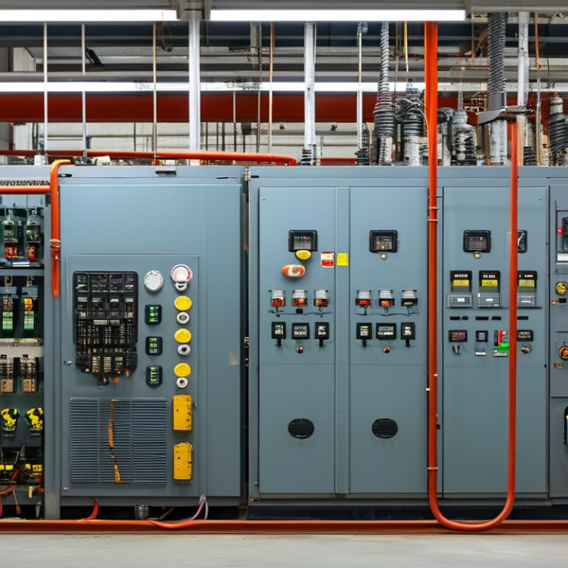
A control transformer is a dedicated transformer for powering control circuits. It usually converts line voltage into a safer, lower control voltage. Common secondary voltages include 24, 120, and 240 volts. Its windings also provide electrical separation between power equipment and sensitive controls. That separation can reduce fault exposure and simplify troubleshooting. IEC 61558-2-2 defines safety requirements for transformers used in control circuits. The standard highlights insulation, temperature rise, and protection requirements. These details matter inside a crowded panel.
The U.S. Department of Energy’s Industrial Motor Systems Market Opportunities Assessment reported that motor systems consume about 68% of industrial electricity. Many of these systems depend on contactors, relays, sensors, and programmable controls. A properly sized control transformer helps those devices operate consistently during motor starting. The VA rating must cover both continuous loads and temporary inrush current. Undersizing is a common mistake. The relay may chatter, or the contactor may fail to pull in firmly. A larger transformer is not automatically better, either. It may increase cost, heat, and available fault energy. Field technicians often check secondary voltage while the machine starts, not only at idle. That practical test can reveal problems that calculations miss. The design still deserves a second look.
A control transformer operates by transferring electrical energy between two coils through a magnetic field. The primary winding receives the incoming voltage. The secondary winding supplies a lower, safer voltage to control devices. Push buttons, relays, sensors, and contactors commonly use this reduced voltage.
Alternating current creates a changing magnetic field in the iron core. That field induces voltage in the secondary winding. The turns ratio determines the output voltage. More primary turns than secondary turns usually produce a lower control voltage. The transformer does not create energy. It changes voltage while preserving power within practical limits.
Small details matter. A technician should compare the nameplate voltage with the measured supply voltage. A wrong connection can damage the coil or prevent a contactor from pulling in. The control circuit also needs suitable fusing and proper grounding practices.
In a noisy cabinet, loose terminals may cause a relay to chatter. That sound is a useful warning, not a minor annoyance.
Heat reveals problems.
The transformer’s VA rating must support the connected load, including the temporary inrush from contactor coils. A unit that works during testing may fail after repeated operation. This is where simple calculations can be misleading. Ambient temperature, wire length, and simultaneous loads also affect performance. Careful measurement at the secondary terminals often explains faults that visual inspection misses.
Why Use a Control Transformer?
Why Is Voltage Reduction Needed in Control Circuits?
Voltage reduction protects people and equipment inside control panels. Power circuits may operate at levels unsuitable for push buttons, sensors, and relay coils. A control transformer supplies a lower, isolated voltage for these devices.
During panel testing, a lower control voltage makes troubleshooting less hazardous. A technician can inspect a loose terminal without working directly on the main supply circuit. Reduced voltage also limits the energy reaching a faulty switch or damaged wire. That matters when metal doors, crowded wiring, and moisture are present.
Safety improves.
Voltage reduction also supports dependable operation. Control components often need stable voltage, not simply available voltage. A properly selected transformer can reduce disturbances from motors and switching loads. It may also prevent excessive coil heating, which can shorten component life. However, voltage reduction is not automatically safer. Incorrect sizing can cause voltage drops, nuisance trips, or unreliable contactor operation. This point is easy to overlook.
I have seen panels where a control circuit worked during testing but failed after several devices operated together. The transformer had enough rated power on paper, yet the wiring distance and inrush current were ignored. Engineers should check load capacity, grounding, insulation, fault protection, and applicable electrical standards. A clear wiring diagram helps, but field verification remains necessary. Small details matter.
| Data Dimension | Typical Value or Condition | Why It Matters in a Control Circuit | Engineering Consideration |
|---|---|---|---|
| Primary input voltage | Common system values include 120 V, 208 V, 240 V, 380 V, 400 V, and 480 V AC | Allows the control circuit to be supplied from the available power system while using a more suitable secondary voltage | The transformer primary rating must match the actual supply voltage and system frequency |
| Typical secondary voltage | 24 V, 48 V, 120 V, or 240 V AC, depending on the equipment design | Provides the voltage required by relays, contactors, timers, pilot devices, valves, and other control components | The selected voltage must match the rated coil or input voltage of every connected device |
| Voltage reduction example | 480 V AC primary reduced to 120 V AC secondary, or 480 V AC reduced to 24 V AC | Reduces the voltage present in control wiring and at operator interfaces | Voltage reduction does not eliminate electrical hazards; proper insulation, grounding, fusing, and enclosure protection remain necessary |
| Electrical isolation | A two-winding control transformer separates the primary and secondary circuits electrically | Helps prevent direct transfer of primary-side voltage to the control circuit and can reduce the effect of certain disturbances | Isolation performance depends on transformer construction, wiring, grounding, and the applicable electrical standard |
| Control-circuit current | For a 100 VA load: approximately 0.83 A at 120 V, 4.17 A at 24 V, ignoring losses | Lower voltage requires higher current for the same power, which affects conductor size and voltage drop | Use the transformer VA rating and calculate secondary current before selecting conductors and overcurrent protection |
| Transformer capacity | Specified in volt-amperes (VA); common control applications may use ratings from tens to several hundred VA | Determines how many control devices can operate simultaneously without excessive voltage sag or overheating | Add the sealed VA of contactor coils and the burden of other devices, then allow suitable design margin |
| Inrush capability | AC contactor and relay coils can draw substantially more power during energization than during steady operation | Helps prevent nuisance voltage dips, contactor chatter, and failure to pull in when several coils operate together | Check both continuous VA and inrush VA requirements shown in the equipment documentation |
| Control wiring distance | Longer cable runs produce greater voltage drop, especially at lower control voltages | Maintains reliable operation of remote sensors, coils, pushbuttons, and interlock circuits | Evaluate conductor resistance, circuit current, installation temperature, and allowable voltage drop |
| Operator and maintenance interface | 24 V AC or 120 V AC may be used depending on the equipment, environment, and applicable requirements | A lower control voltage can simplify the design of pushbutton stations, indication circuits, and service interfaces | Choose the control voltage based on component availability, site practice, accessibility, and the required safety standard |
| Protection requirements | Primary and secondary overcurrent protection are normally selected according to transformer ratings and local electrical rules | Limits damage caused by short circuits, overloads, or wiring faults | Fuse or breaker selection must consider transformer inrush, conductor ampacity, interrupting rating, and applicable codes |
| Operating frequency | Most industrial control transformers are designed for 50 Hz, 60 Hz, or both | The correct frequency supports the specified magnetic performance and temperature rise | Never assume frequency compatibility; verify the transformer nameplate and installation requirements |
| Main design benefit | A dedicated, isolated, and appropriately rated control power source | Improves control-system compatibility, serviceability, and operational reliability | A transformer is only one part of the control-power design; grounding, wiring, protection, and component ratings must be coordinated |
Note: Values shown are typical engineering examples rather than universal requirements. The final control-transformer selection should be based on the equipment nameplate, calculated load, inrush demand, installation conditions, and applicable electrical codes.
A control transformer provides a safer, more stable voltage for operating industrial control circuits. It separates control wiring from the main power circuit. This isolation can reduce shock risks and limit damage during equipment faults. It also allows low-voltage devices to control higher-voltage motors, contactors, and relays. In practical installations, this makes troubleshooting clearer. A technician can test the control side without working directly on the motor supply. That small difference matters during maintenance.
A properly sized transformer helps prevent voltage drops when several coils energize at once. Stable voltage supports reliable starting, stopping, signaling, and emergency shutdown functions. It can also simplify panel design when available supply voltage does not match control components. However, a transformer is not a cure for poor engineering. Incorrect sizing may cause overheating, nuisance trips, or weak contactor operation. I have seen control faults blamed on switches when the real problem was an overloaded transformer. The calculation deserves attention.
Tips: Check the primary and secondary voltages carefully. Add the inrush VA of contactors and solenoids, not only their holding VA. Leave practical capacity for future devices. Provide overcurrent protection on the appropriate circuits. Keep control wiring labeled and physically separated from noisy power conductors. Test the transformer under realistic load conditions. Do not rely only on an unloaded voltage reading. Safety procedures and local electrical requirements still apply.
Why Use a Control Transformer?
How Should the Right Control Transformer Be Selected?
A control transformer provides a stable, isolated voltage for relays, contactors, sensors, and control boards. This separation can improve operator safety and reduce disturbances from motor circuits. However, choosing one requires more than matching the panel’s available voltage.
Start by confirming the primary voltage, secondary voltage, frequency, and required VA rating. Check the equipment drawings and measure the actual supply when possible. A 120-volt control circuit may appear simple, but contactors can draw high inrush current. Add the inrush VA of all devices that may operate together. Then include a practical margin, often 20% to 30%. Too little capacity causes voltage sag and unreliable starting. Too much capacity can increase cost and panel space.
Consider duty cycle, ambient temperature, insulation, terminals, enclosure type, and installation location. A transformer near a hot drive cabinet may need thermal derating. Verify the secondary grounding method and required protective devices against applicable electrical codes. In field testing, technicians should measure the secondary voltage during simultaneous operation, not only at no load. That detail is easy to miss. I would also recheck the calculation after future sensors or valves are added. The first estimate may be correct today, but control systems rarely stay unchanged.